描述
| SKiiP 2414 GB17E4-4DUK310 | ||||||||
| Absolute Maximum Ratings Symbol Conditions |
Values | Unit | ||||||
| System | ||||||||
| VCC 1) | Operating DC link voltage | 1300 | V | |||||
| Visol | DC, t = 1 s, each polarity | 5600 | V | |||||
| It(RMS) | per AC terminal, rms, sinusoidal current | 500 | A | |||||
| Imax (peak) | max. peak current of power section | 3600 | A | |||||
| IFSM | Tj = 175 °C, tp = 10 ms, sin 180° | 15885 | A | |||||
| I²t | Tj = 175 °C, tp = 10 ms, diode | 1262 | kA²s | |||||
| SKiiP® 4 | fout | fundamental output frequency (sinusoidal) |
1 | kHz | ||||
| pw | water pressure | 10 | bar | |||||
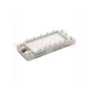
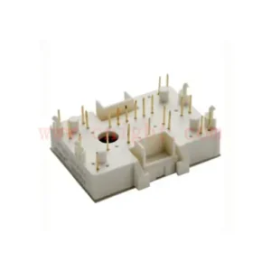
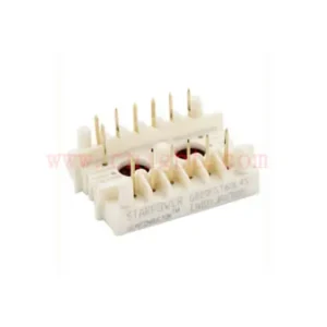
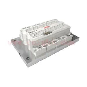
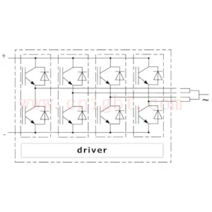
| 2-pack-integrated intelligent Power SystemSKiiP 2414 GB17E4-4DUK310Features* • Intelligent Power Module • Integrated current and temperature measurement • Integrated DC-link measurement • Solder free power section • IGBT4 and CAL4F technology • Safety isolated switching and sensor signals • Digital signal transmission • CAN Interface • 100% tested IPM • RoHS compliant • UL file no. E242581 Typical Applications • Renewable energies • Traction • Elevators • Industrial drives Remarks For further information please refer to SKiiP®4 Technical Explanation Footnotes |
Vw | maximum flow rate with standard turbulators3) , minimum 2 channels used for this flow rate |
9 | l/min | ||||
| Tcoolant | inhibitor 1% – 4% | 70 | °C | |||||
| Tstg | storage temperature | -40 … 85 | °C | |||||
| IGBT | ||||||||
| VCES | Tj = 25 °C | 1700 | V | |||||
| IC | Tj = 175 °C | Ts = 25 °C | 3225 | A | ||||
| Ts = 70 °C | 2600 | A | ||||||
| ICnom | 2400 | A | ||||||
| Tj 2) | junction temperature | -40 … 175 | °C | |||||
| Diode | ||||||||
| VRRM | Tj = 25 °C | 1700 | V | |||||
| IF | Tj = 175 °C | Ts = 25 °C | 2362 | A | ||||
| Ts = 70 °C | 1869 | A | ||||||
| Tj 2) | junction temperature | -40 … 175 | °C | |||||
| Driver | ||||||||
| Vs | power supply | 19.2 … 28.8 | V | |||||
| ViH | input signal voltage (high) | Vs + 0.3 | V | |||||
| dv/dt | secondary to primary side | 75 | kV/µs | |||||
| fsw | switching frequency | 10 | kHz | |||||
| Characteristics Symbol Conditions |
min. typ. max. | Unit | ||||||
| IGBT | ||||||||
| VCE(sat) | IC = 2400 A at terminal |
Tj = 25 °C | 2.12 2.43 | V | ||||
| Tj = 150 °C | 2.64 2.95 | V | ||||||
| VCE0 | Tj = 25 °C | 1.10 1.20 | V | |||||
| Tj = 150 °C | 1.00 1.10 | V | ||||||
| rCE | at terminal | Tj = 25 °C | 0.42 0.51 | mΩ | ||||
| Tj = 150 °C | 0.68 0.77 | mΩ | ||||||
| Eon + Eoff | IC = 2400 A Tj = 150 °C |
VCC = 900 V | 1780 | mJ | ||||
| VCC = 1300 V | 2840 | mJ | ||||||
| Rth(j-s) | per IGBT switch | 0.0138 | K/W | |||||
| Rth(j-r) | per IGBT switch | 0.0107 | K/W | |||||